
Page 65 - 360.revista de Alta Velocidad - Nº 5
P. 65
Current situation and prospects of electric traction systems used in High-Speed railways
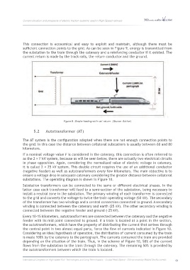
This connection is economical and easy to exploit and maintain, although there must be
sufficient connection points to the grid. As can be seen in Figure 9, energy is transmitted from
the substation to the train through the catenary and a reinforcing conductor if it existed. The
current return is made by the track rails, the return conductor and the ground.
Figure 9. Simple feeding with rail return. (Source: Author).
5.2 Autotransformer (AT)
The AT system is the configuration adopted when there are not enough connection points to
the grid. In this case the distance between collateral substations is usually between 60 and 80
kilometers.
If a nominal voltage value is considered in the catenary, this connection is often referred to
as the 2 × kV system, because as will be seen below, there are actually two electrical circuits
in phase opposition. Again, considering the normalized value of electric voltage in catenary,
it is called 2 × 25 kV system. This double circuit requires the use of an additional conductor
(negative feeder) as well as autotransformers every few kilometers. The main objective is to
ensure a voltage drop in adequate catenary considering the greater distance between collateral
substations. The operating diagram is shown in Figure 10.
Substation transformers can be connected to the same or different electrical phases. In the
latter case each transformer will feed to a semi-section of the substation, being necessary to
install a neutral zone in the substation. The primary winding of each transformer is connected
to the grid and converts the voltage to twice the train operating voltage (50 kV). The secondary
of the transformer has two windings and a central connection connected to ground. A secondary
winding is connected between the catenary and earth (25 kV). The other secondary winding is
connected between the negative feeder and ground (-25 kV).
Every 10-15 kilometers, autotransformers are connected between the catenary and the negative
feeder with its mid point connected to ground. If a train is located at a point in the section,
the autotransformers, which have the property of distributing the current that arrives through
the central point in two almost equal parts, force the flow of currents indicated in Figure 10.
Considering an ideal hypothesis of operation, the distribution of current consumed by the train
is made 100% by the catenary to the pantograph. The currents consumed the train are provided
depending on the situation of the train. Thus, in the scheme of Figure 10, 50% of the current
flows from the substation to the train through the catenary. The remaining 50% is provided by
the autotransformers between which the train is located.
International Congress on High-speed Rail: Technologies and Long Term Impacts - Ciudad Real (Spain) - 25th anniversary Madrid-Sevilla corridor 63