
Page 68 - 360.revista de Alta Velocidad - Nº 5
P. 68
Martínez Acevedo, José Conrado. Berrios Villalba, Antonio. Peregrín García, Eugenio.
To determine the load of the electrification system, simulation software has been used to
determine the power demanded or returned by each train at each time point and its position
according to the parameters that influence the energy consumption. After determining the
power and its position in the track of each train for each instant, and therefore the locations of
the loads in the electric circuit, the behavior of the electrification system has been determined.
Depending on the time step used in the simulator, the static or dynamic behavior of the system
can be analyzed.
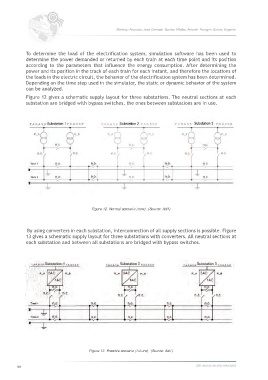
Figure 12 gives a schematic supply layout for three substations. The neutral sections at each
substation are bridged with bypass switches, the ones between substations are in use.
Figure 12. Normal scenario (now). (Source: Adif).
By using converters in each substation, interconnection of all supply sections is possible. Figure
13 gives a schematic supply layout for three substations with converters. All neutral sections at
each substation and between all substations are bridged with bypass switches.
Figure 13. Possible scenario (future). (Source: Adif).
66 360.revista de alta velocidad