
Page 62 - 360.revista de Alta Velocidad - Nº 5
P. 62
Martínez Acevedo, José Conrado. Berrios Villalba, Antonio. Peregrín García, Eugenio.
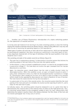
Converter Catenary Voltage Harmonic Catenary
Power Supply Power Rating Neutral Sections and Frequency Compensation Short Circuit
(PerUnit Load) Regulation Protection
Normal - Compulsory No No Passive
SVC 0.58 Compulsory No No Passive
STATCOM 0.58 Compulsory No Yes Passive
Full-Power
Converter 1.0 Can be omitted Yes Yes Active
Cophase Supply 0.5 Can be omitted No Yes Passive
Table 1. A comparison of different feeding systems of AC railways (Source: [1].
4. Another use of Power Electronics: introduction of a static switching system
for the operation of neutral sections
Currently some administrators are starting to try static switching systems to allow the training
3
making the transition between electrical phases directly, without being affected in any way and
with the aim of improving the operating capacity of the exploitation.
These types of systems use switches on each side of the neutral section, which are represented
by semiconductor equipment that allow carrying out a switching in a very short space of time.
A very important characteristic of this type of switching is that the exact position of the train
should be born in mind.
The operating principle of the system would be as follows (Figure 8):
• The train that is coming along catenary 1 is detected by a detection system that informs the
switching system of the next entry of the train into the neutral section.
• At this moment, a close command is established to switch 1 so that the de-energised section
is powered at voltage V1. The train does not receive the open command from the traction
disconnector at any time.
• Again, the detection system should detect that the train is totally situated inside the
deenergised section. When this condition occurs, an open command is issued on switch 1
and a close command on switch 2 so that the de-energised section is powered at voltage
V2. This process is short enough for the train not to detect a lack of voltage in the catenary
(which would involve opening the disconnector) and there is therefore no loss of traction.
The train leaves the neutral section fed by electrical phase 2.
• In a given point of the exit of the neutral section, the detection system identifies the total
passing of the train and starts to normalise the neutral section (opening of switch 2), and is
ready for the next train to pass.
As indicated above, the switching system should be designed to act in a given time that is
determined by the characteristics of the material that circulates on the High-Speed Line. Thus,
if a detection system based on electromagnetic pedals is used, the main characteristic that
determines the system’s reaction time is the distance between the first wheel of the train and
the nearest pantograph that it may carry in service.
3 It should be pointed out that the detection system may be represented by a track circuit specially designed for this function (as
is the case of the Japanese system), or by a series of electromagnetic pedals that detect the position of the train wheel (system
used in test by Adif).
60 360.revista de alta velocidad