
Page 57 - 360.revista de Alta Velocidad - Nº 5
P. 57
Current situation and prospects of electric traction systems used in High-Speed railways
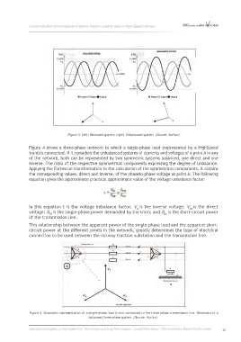
Figure 3. Left) Balanced system; right) Unbalanced system. (Source: Author).
Figure 4 shows a three-phase network to which a single-phase load (represented by a HighSpeed
train) is connected. If it considers the unbalanced systems of currents and voltages of a point A in any
of the network, both can be represented by two symmetric systems balanced, one direct and one
inverse. The ratio of the respective symmetrical components expressing the degree of unbalance.
Applying the Fortescue transformation to the calculation of the symmetrical components, it obtains
the corresponding values, direct and inverse, of the phaseto-phase voltage at point A. The following
equation gives the approximate practical approximate value of the voltage unbalance factor:
In this equation τ is the voltage imbalance factor; V is the inverse voltage; V is the direct
0d
0i
voltage; S is the single-phase power demanded by the train; and S is the short-circuit power
TR
CC
of the transmission line.
This relationship between the apparent power of the single-phase load and the apparent short-
circuit power at the different points in the network, greatly determines the type of electrical
connection to be used between the railway traction substation and the transmission line.
Figure 4. Schematic representation of a single-phase load (train) connected to the three-phase transmission line. Schematic of a
balanced three-phase system. (Source: Author).
International Congress on High-speed Rail: Technologies and Long Term Impacts - Ciudad Real (Spain) - 25th anniversary Madrid-Sevilla corridor 55