
Page 274 - 360.revista de Alta Velocidad - Nº 5
P. 274
Álvarez, Fernando. Balmaseda, Lucía. Gallego, Inmaculada. Rivas , Ana. Sánchez-Cambronero, San
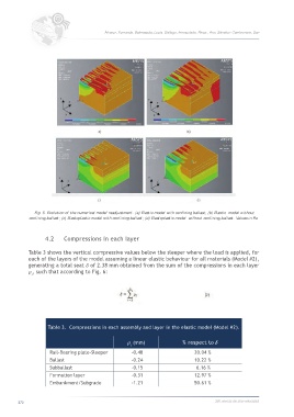
Fig. 5. Evolution of the numerical model readjustment. (a) Elastic model with confining ballast; (b) Elastic model without
confining ballast; (c) Elastoplastic model with confining ballast; (d) Elastoplastic model without confining ballast. Values in Pa.
4.2 Compressions in each layer
Table 3 shows the vertical compressive values below the sleeper where the load is applied, for
each of the layers of the model assuming a linear elastic behaviour for all materials (Model #2),
generating a total seat of 2.38 mm obtained from the sum of the compressions in each layer
, such that according to Fig. 6:
Table 3. Compressions in each assembly and layer in the elastic model (Model #2).
(mm) % respect to
Rail-Bearing plate-Sleeper -0.48 20.04 %
Ballast -0.24 10.22 %
Subballast -0.15 6.16 %
Formation layer -0.31 12.97 %
Embankment/Subgrade -1.21 50.61 %
272 360.revista de alta velocidad