
Page 273 - 360.revista de Alta Velocidad - Nº 5
P. 273
Calculation and rational dimensioning of railway infrastructure materials using numerical modelling
The second of the strategies did not make sense since it was contemplated to compare the
elastic model with the elastoplastic. Therefore, it was decided to apply the first of them to
check if really, removing the top layer would influence the vertical stresses that occurred in
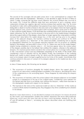
the model. Fig. 5 shows the different steps that were performed in such a strategy, where
compression stresses has negative sign and tractions stresses have positive sign: Fig. 5a shows
the platform model with confining ballast that assumes linear elastic behaviour for all materials,
being able to observe traction stresses in the area next to the sleeper where the load is applied
and the adjacent ones, above the support plane with the ballast, and in areas close to the limits
in the numerical model domain; If we eliminate the confining ballast and continue assuming an
elastic behaviour, Fig. 5b, the traction stresses in the area next to the loaded sleeper disappear
above the support plane of the sleeper, where they no longer oppose the compressions and they
increase their value below the loaded sleeper but, in the lower and top zone to the support
plane of the adjacent sleepers, the tractions continue to persist and continue to the limit
of the model, possibly by a “distortion” of the numerical model; Considering now to assume
an elastoplastic behaviour for the granular materials together with the presence of confining
ballast in the sleepers, we have what is shown in Fig. 5c, where now next to the loaded sleeper,
despite having considered a cohesion value ( = 0), tractions appear above the contact plane
of the sleeper, possibly due to the ballast that confines the sleepers, whereas in the adjacent
sleepers, the tractions persist below and above the contact plane due to arrange nodes coupled
to the cross-ballast contact and are eliminated completely in the limits of the model when
considering a value of cohesion null for the ballast; Finally, the elimination of the confining
ballast now results in what is shown in Fig. 5d, where now the tractions disappear completely
next to the sleeper where the load is applied and in the limits of the model, nevertheless they
continue present In the plane of contact of the sleepers adjacent to the loaded one due to the
coupled nodes.
In view of these results, the following can be stated:
1. The occurrence of tractions alongside the loaded sleeper, above the support plane, is
present in all cases where confining ballast is available in the sleepers, decreasing the value
of the compressions in the underlying layers. These disappear by mistrusting the sleepers
in all cases.
2. The occurrence of tractions under the contact plane in the sleepers adjacent to the loaded
sleeper is a consequence of the use of the coupled nodes. Considering a zero cohesion for
the ballast and that there is no ballast that confines the sleepers, makes them decrease in
the elastoplastic models with respect to the elastics.
3. The tractions in the limits of the numerical model are due to a "distortion" of the results as
a result of finite element modelling and, they disappear only when considering null cohesion
in the ballast.
Based on these observations, it was decided to analyse and compare the results obtained
by the elastic and elastoplastic models that better simulated the tenso-deformational
behaviour, which were the ones that did not have confining ballast, Models #2, #4, #6,
#7 and #8 defined in Table 1, remaining the others discarded when not fulfilling this
condition.
International Congress on High-speed Rail: Technologies and Long Term Impacts - Ciudad Real (Spain) - 25th anniversary Madrid-Sevilla corridor 271