
Page 308 - 360.revista de Alta Velocidad - Nº 5
P. 308
Balmaseda, Lucía. Gallego, Inmaculada. Sánchez-Cambronero, Santos. Rivas, Ana.
unknown, iteration is necessary to obtain a converged value of the stiffness based on a certain
static load value.
Different types of infrastructures were selected. For each infrastructure, the static stiffness
was calculated by entering the static load in the software and consecutively applying it to
four sleepers to simulate the passage of an axle. With the static stiffness value obtained, an
initial dynamic overload value was calculated. With the total value of the load, the model was
recalculated and an initial dynamic stiffness value was obtained. This process was iterated
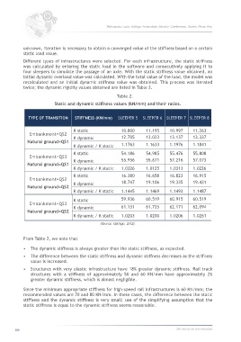
twice; the dynamic rigidity values obtained are listed in Table 2.
Table 2.
Static and dynamic stiffness values (kN/mm) and their ratios.
TYPE OF TRANSITION STIFFNESS (KN/mm) SLEEPER 5 SLEEPER 6 SLEEPER 7 SLEEPER 8
K static 10.800 11.195 10.997 11.263
Embankment=QS2
K dynamic 12.705 13.023 13.137 13.337
Natural ground=QS1
K dynamic / K static 1.1763 1.1633 1.1976 1.1841
K static 54.186 54.985 55.476 55.808
Embankment=QS3
K dynamic 55.956 55.671 57.216 57.073
Natural ground=QS1
K dynamic / K static 1.0326 1.0125 1.0313 1.0226
K static 16.380 16.658 16.823 16.915
Embankment=QS2
K dynamic 18.747 19.106 19.335 19.431
Natural ground=QS2
K dynamic / K static 1.1445 1.1469 1.1493 1.1487
K static 59.936 60.519 60.915 60.519
Embankment=QS3
K dynamic 61.151 61.735 62.171 62.094
Natural ground=QS2
K dynamic / K static 1.0203 1.0200 1.0206 1.0261
(Source: Gallego, 2012).
From Table 2, we note that
• The dynamic stiffness is always greater than the static stiffness, as expected.
• The difference between the static stiffness and dynamic stiffness decreases as the stiffness
value is increased.
• Structures with very elastic infrastructure have 18% greater dynamic stiffness. Rail track
structures with a stiffness of approximately 50 and 60 KN/mm have approximately 2%
greater dynamic stiffness, which is almost negligible.
Since the minimum appropriate stiffness for high-speed rail infrastructures is 60 KN/mm; the
recommended values are 70 and 80 KN/mm. In these cases, the difference between the static
stiffness and the dynamic stiffness is very small; use of the simplifying assumption that the
static stiffness is equal to the dynamic stiffness seems reasonable.
306 360.revista de alta velocidad