
Page 76 - 360.revista de Alta Velocidad - Nº 5
P. 76
Piqueras, Anibal. Saura, Joan. Paños, Francisco.
In the homologation process a wagon series Sgnss (4 axle wagon, 920 mm wheel, bogie Y21,
for transport of containers) and a wagon series Laaers (2 axle half wagon, 760 mm wheel, for
transport of cars) have been used.
One of the keys of this OGI wheelset refers to the fact that it is easily interchangeable. This
means that it does not matter the series of wagon we are interested to equip with the OGI cer-
tified wheelset 920 mm or 760 mm.
2.3.1 The homologation process of the OGI variable gauge system
The homologation process for a variable gauge system is highly regulated in the EU and it also
exists in Spain a great experience in the national variable gauge regulation due to its different
1668 mm track gauge.
The legislation followed in the OGI project has been the Spanish ETH ("Especificación Técnica
de Material Rodante Ferroviario: vagones"). The certification plan was in accordance with ETH
and not with TSI because "variable gauge system" was an open point at the moment the homo-
logation process started.
The process to homologate a variable gauge system consists mainly on:
• The design review.
In the design review are analysed the functionality of the system including calculations of the
components according to the EU standards (e.g. wheels or axles), the locking mechanism, the
thermal effect of braking on the variable-gauge systems, the maintenance plan and the study
of functional reliability RAMS.
• Laboratory tests - fatigue tests to validate the locking system.
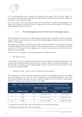
The laboratory tests have consisted on the determination of the fatigue strength of a variable-
gauge running gear. In our case, the bench consisted on a rotational bending test where they
were applied dynamic and static forces at a speed of 50km/h. The 10 million of cycles where
divided in 3 stages, in accordance with the next table:
Table 1. Phases, cycles and forces of the variable gauge system laboratory test
Vertical force [kN] Transverse force [kN]
Phase Number of cycles Static Dynamic Static Dynamic
I 6·106 P ± 0,5 P at 4 Hz 0 ± 0,3 P at 2 Hz
II 2·106 P ± 0,6 P at 4 Hz 0 ± 0,36 P at 2 Hz
III 2·106 P ± 0,7 P at 4 Hz 0 ± 0,42 P at 2 Hz
* Prepresents the static axle load corresponding to the maximum payload
* Frequencies reflected is for a 50 km/h speed.
74 360.revista de alta velocidad